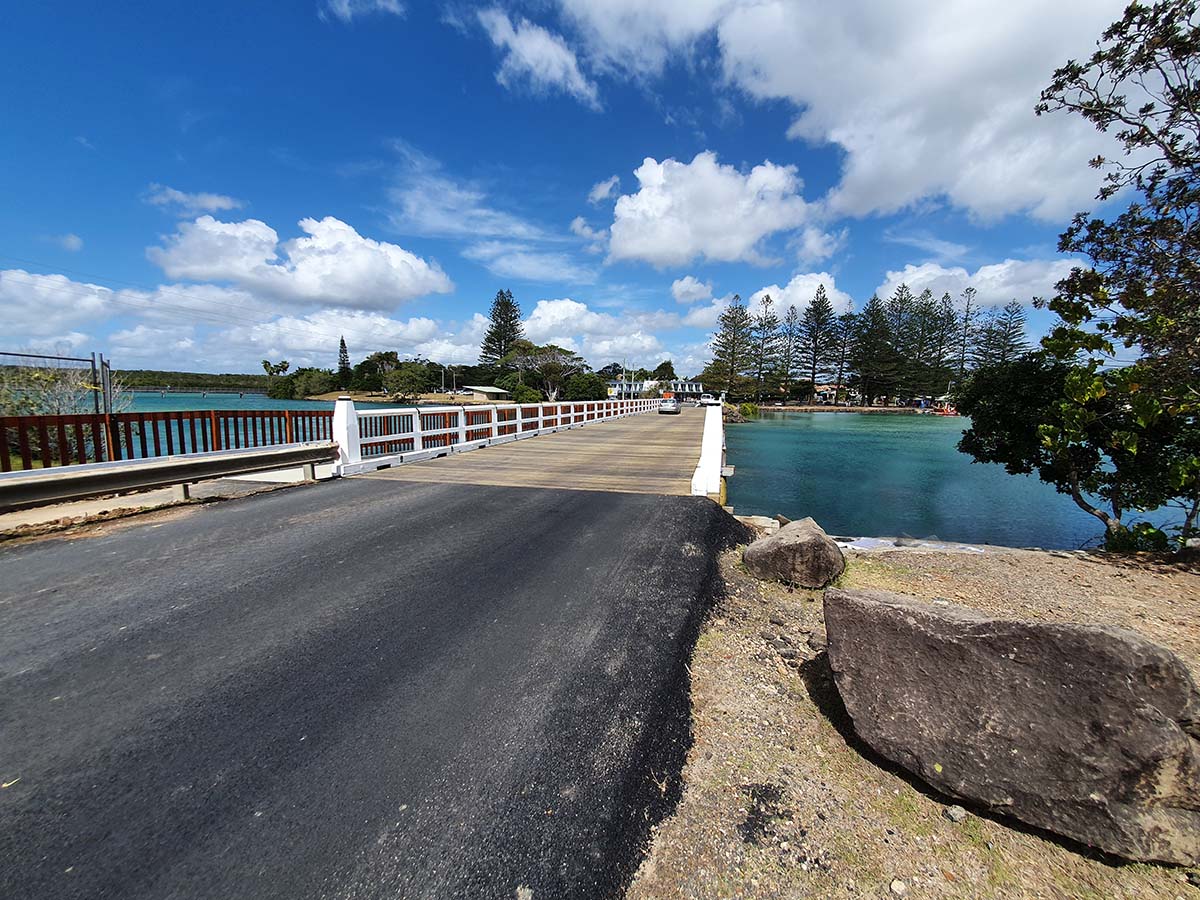
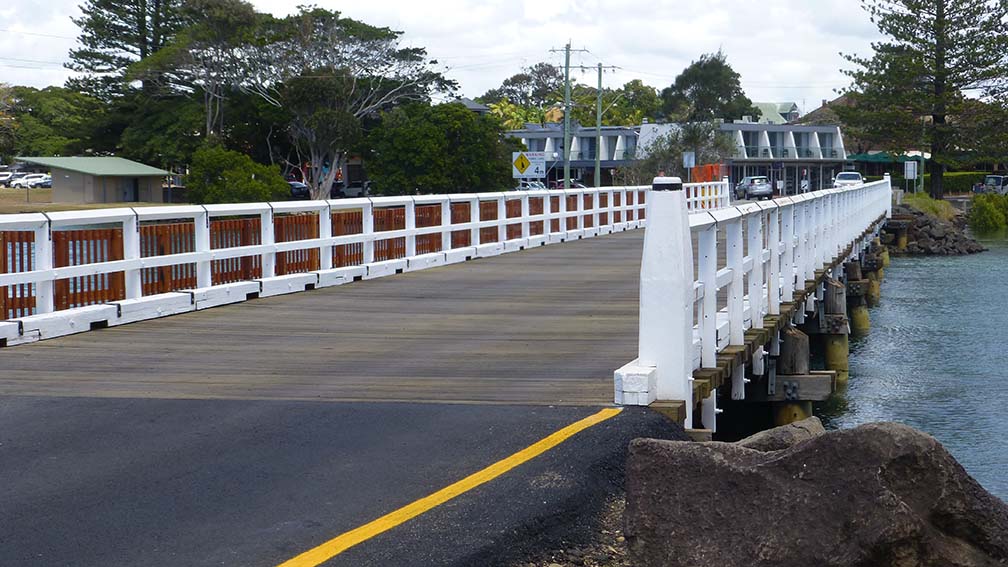
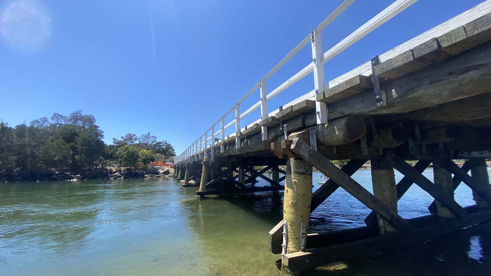
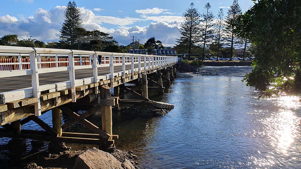
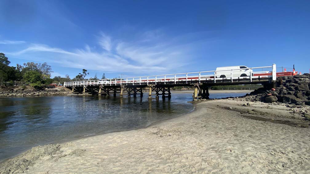
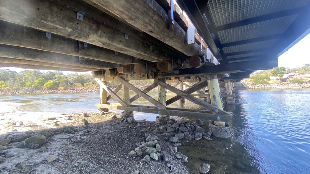
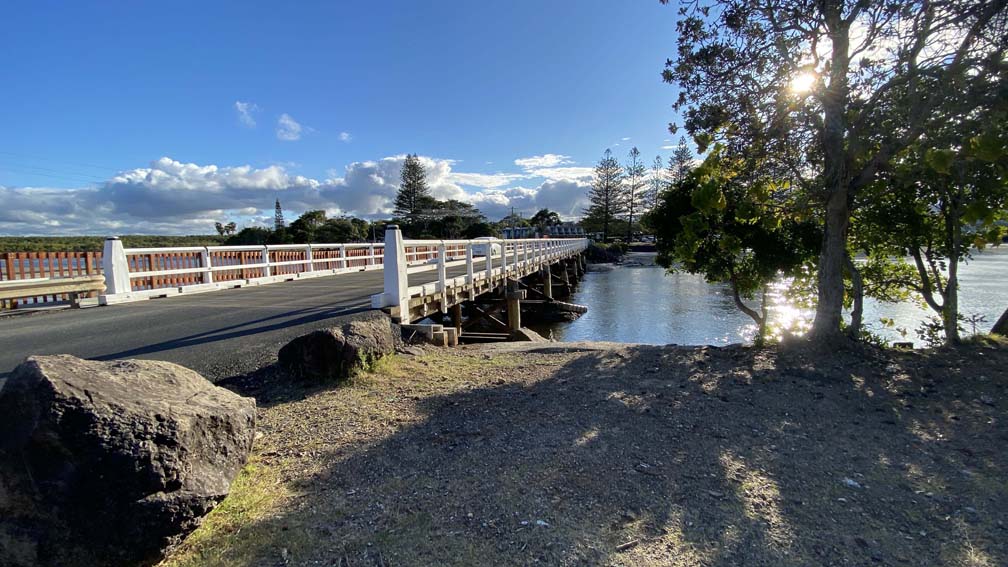
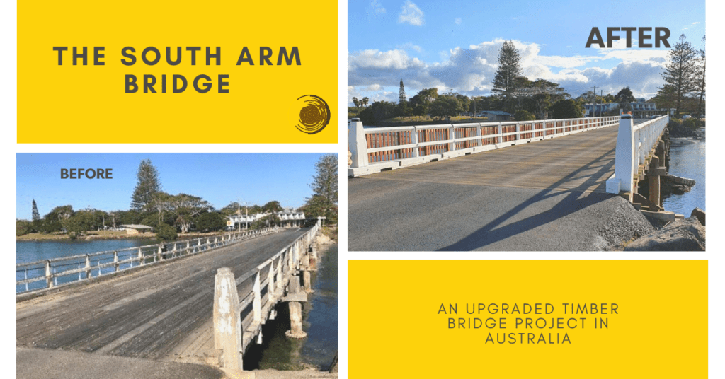
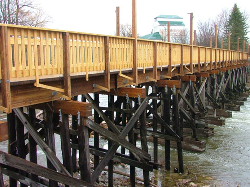
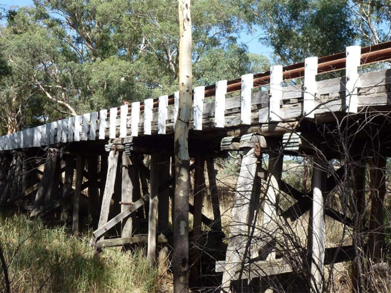
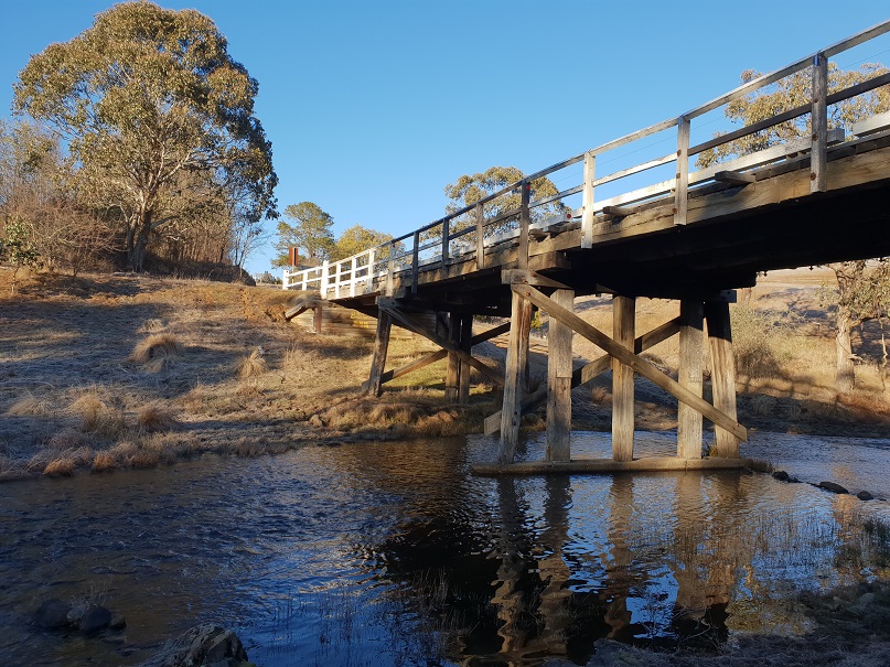
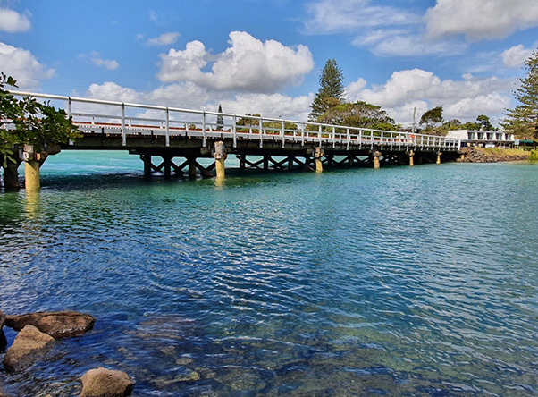
Brunswick Heads on the Northern NSW coastline is a small idyllic town, separated from the ocean shore by the tidal Simpsons Creek. The old timber bridge spanning the river is an iconic symbol of the town since it symbolised the progress of the town from a logging shipping port to a popular tourist destination, renowned for its surfing and picnic spots. The bridge was built in 1958-9 transporting rock wall boulders to build the south wall breakwater and the local community love the character of the bridge. The South Arm bridge is a 7 spanned, 6.15m wide x 63m long bridge supported on timber piles that have been encased with concrete sleeves and sand to protect them from marine borers (Teredo navalis) damage. With a community heavily invested in environmental issues, recycling and natural well-being, it made perfect sense to restore and upgrade the bridge back to its former glory.

The original South Arm Bridge, before the upgrade – 2017
A Historic Bridge
In 2019, Wood Research and Development (WRD) performed a Level 3 bridge inspection, assessing and providing structural recommendations on upgrading the bridge from 10T to 44T. With a stockpile of logs and timbers from past demolished bridges, Council had WRD to perform non-destructive testing to create a list of reusable timbers for the bridge.
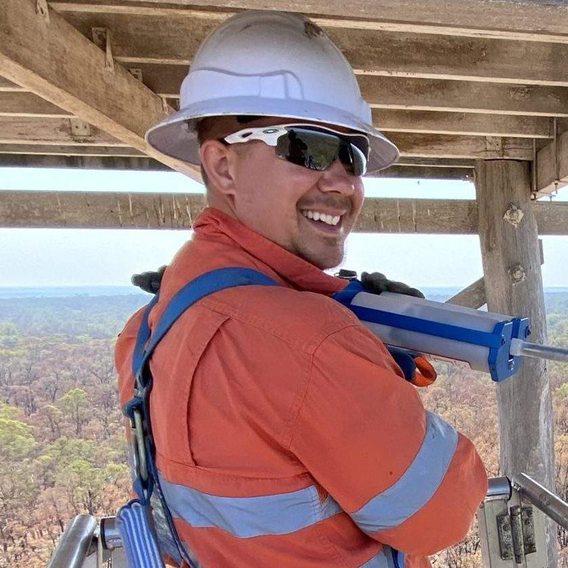
In the same year, Timber Restoration Services (TRS) won the contract to upgrade the 63m bridge from 10 tonne to 44 tonne traffic loading. Part of the rehabilitation process was to recycle the existing timbers where possible and reuse the log timbers at the Council stockyard. To ensure the recycled timber is given the best protection, wherever TRS made cuts or drilled holes, Copper Naphthenate Oil Emulsion (CN oil) was applied and a paraffin-based sealant, Anchorseal® was used to seal the cuts. The final touch was to diffuse all the timbers with borate salt rods, Decaystop® to inhibit fungi growth, allowing easy access to maintain the bridge elements.
The Deck
One area of major decay concern was the existing two-leaf deck on the bridge. Once the upper longitudinal boards were lifted, it became obvious that the bottom transverse deck boards had been damaged by termites and decay. With a two leaf deck system, moisture gets trapped between the deck layers and slowly decays the underlying boards without anyone seeing this happen. Having coach screws secure the top running boards to the boards underneath meant there was a pathway for moisture to penetrate and get between and into the underlying transverse deck boards.
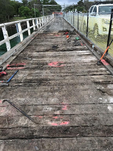
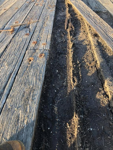
The two layer system effectively traps grit and doesn’t allow air to circulate and dry the boards. Constant moisture trapped between timbers is going to perpetuate a decay scenario. So the lesson learnt is that a deck with overlay boards on transverse boards is a haven for hidden degradation. The best solution is to have a single layer of transverse deck boards with a gap between to allow air to circulate, debris to fall through and keep the timber dry.
The Piles
The existing piles had been encased with a concrete shell and sand packed between. The shells were about 60mm thick and looked like a concrete pipe without the flared flange. This is an innovative way to protect the timber piles from marine borers and actually, was quite effective except … over time, the salt environment corroded the reinforcement mesh which cracked the concrete and caused the shell to break, allowing water in. Slowly, the concrete fell apart, the tide washed out the sand and marine borers found a home. Some of the piles were completely encased in concrete which later proved to be the worst possible treatment to the timber. Once removed, the timber was soft with decay and a reduced density since the concrete kept the timber moist.
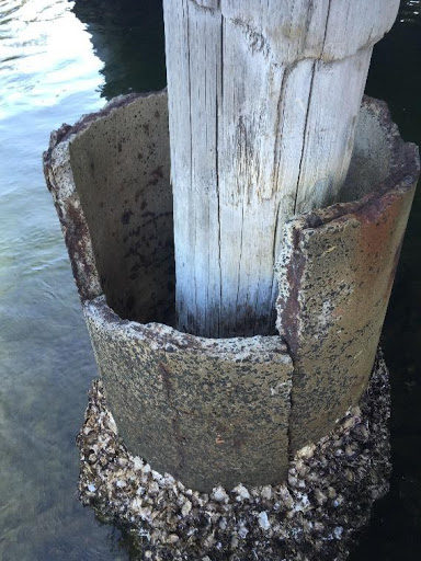

Using the non-destructive and extremely accurate Stress Wave Timer (SWT), compressive wave readings were taken down the height of the pile to find where good solid wood could be sourced to anchor pile posting.
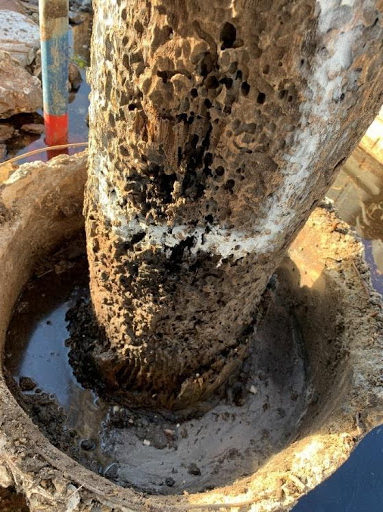
As can be seen from the photo to the left, one would assume the borer damage would need to be cut out but using the SWT, the results highlighted that the borer damaged section was actually very solid and as such, the pile posting could occur above the borer damaged section. The SWT equipment takes the guesswork and assumptions out of assessing the damaged timber and finding the “good” wood.
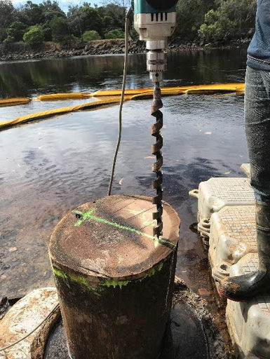
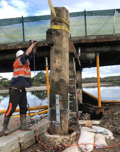
Once cut, the posting section is lowered into position, plumbed and marked for the jointing plates. Two holes are vertically drilled into end grain for shear pins and a liberal coat of Copper Naphthenate(CN) oil is applied prior to jointing.
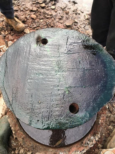
Once the shear pins have been inserted and the join posting plates have been installed, the headstock is positioned and attached to the new tongue. To structurally reinforce the pile and protect it from further borer damage, TRS triple-wrapped the pile as the final segment of the pile posting remedy. Once wrapped, the piles are diffused in a spiral pattern down the pile length.

Good Construction Practices
Finding “Good Wood”
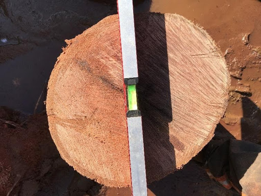
To highlight the effectiveness of the SWT, as measurements were taken down the length of the pile to find “good wood”, the pile was lopped where the results reflected the possibility of a potential cut zone. The pictures below represent some of the issues where moisture entrapment shows the potential for ongoing decay is not addressed and where reduced density can be missed if boring is used as the measure.
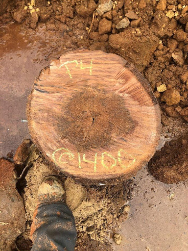
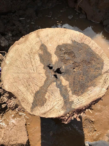
Both piles showed results that indicated a possible cavity but was actually found to be significantly reduced specific gravity zones. While there is annulus to work with for structural binding, the potential for the decay to spread is too great. With more SWT readings for guidance, the accepted cut profile was another 900mm below.
Sealing cuts
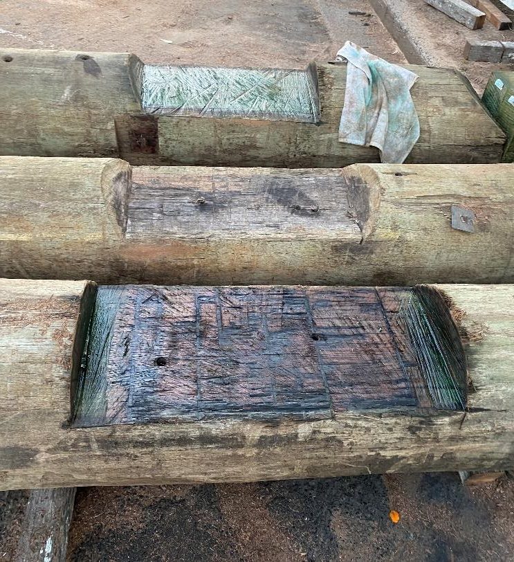
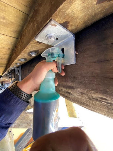
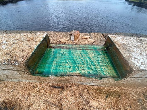
As a standard TRS good construction practice, drill holes are sprayed with Copper Naphthenate (CN) oil, end cuts and notches are coated with CN oil and sealed with a paraffin-based sealant Anchorseal®.
Copper Naphthenate is a fungicidal solution to inhibit fungi growth. Anchorseal® inhibits rapid moisture loss from the end grain and exposed wood, mitigating shrinkage checks.
Sloping Cuts
The development of the stress checks at the notch (re-entrant cracks) occur due to the abrupt change in the stiffness of the log girder at the notch zone. The stiffness of the girder is directly related to the depth and the timber’s inherent characteristic strength – stiffness being the ability of the timber to resist movement.


As the log girder carries traffic loads, the notched section (A) over the headstock and the full depth girder section (B) will move differently. Because A is a much shallower depth, the amount of stiffness in A will be far less than the stiffness of the deeper section B therefore section A will flex more than section B. That differential stiffness in the two sections of the log girder causing differential movement generates tension stress separating the fibres at the zone of change (notch), causing a re-entrant crack to occur.
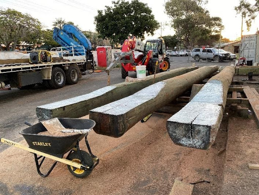
When there is a 90 degree notch as shown in the photos above, the development of the tension stresses will obviously occur at the juncture. When slope cuts are introduced, the gradual slope of the cut reduces the differential stiffness effects along the “notch zone”.
A 1:4 slope cut was deemed sufficient to reduce this problem by most authorities in the 1940’s and onwards but re-entrant cracks were still occurring. Through decades of experience and observations, TRS recommends that slope cuts be set at 1:6 to mitigate the propogation of tension stress checks. By creating a more gradual slope cut, the differential stiffness effects are less pronounced and the likelihood for re-entrant cracking to occur is very low.
Combining TRS’ good construction practice of applying CN oil and Anchorseal® with the more gradual slope cut of 1:6, moisture loss from the exposed slope cut and differential stiffness checking are significantly reduced thereby eliminating this issue in log girders.
Horizontal Connections
Benjamin Franklin said it best: “Prevention is better than the cure”.
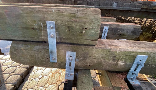
Eliminating vertical throughbolts in a timber bridge increases the longevity of the bridge threefold. By not having vertical penetrations through the wood, particularly log elements, there is little opportunity for the moisture to get to the log core and commence the decay process where it cannot dry out easily.
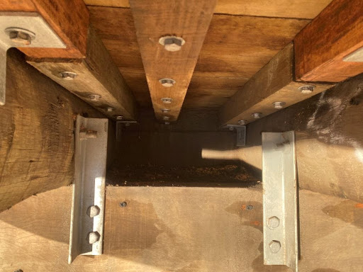
Whilst using CN oil, Anchorseal®, and Decaystop® borate salt rods are all excellent products to inhibit fungal growth, good design, and construction practices will always provide the best preventative measures. Horizontal connections binding the elements reduce the opportunity for moisture to penetrate. Remember to allow for shrinkage with slotted holes in the steel connections.
To keep the transverse deck in tip top condition, the coach screws are driven from underneath thereby ensuring no penetrations into the deck from the top.
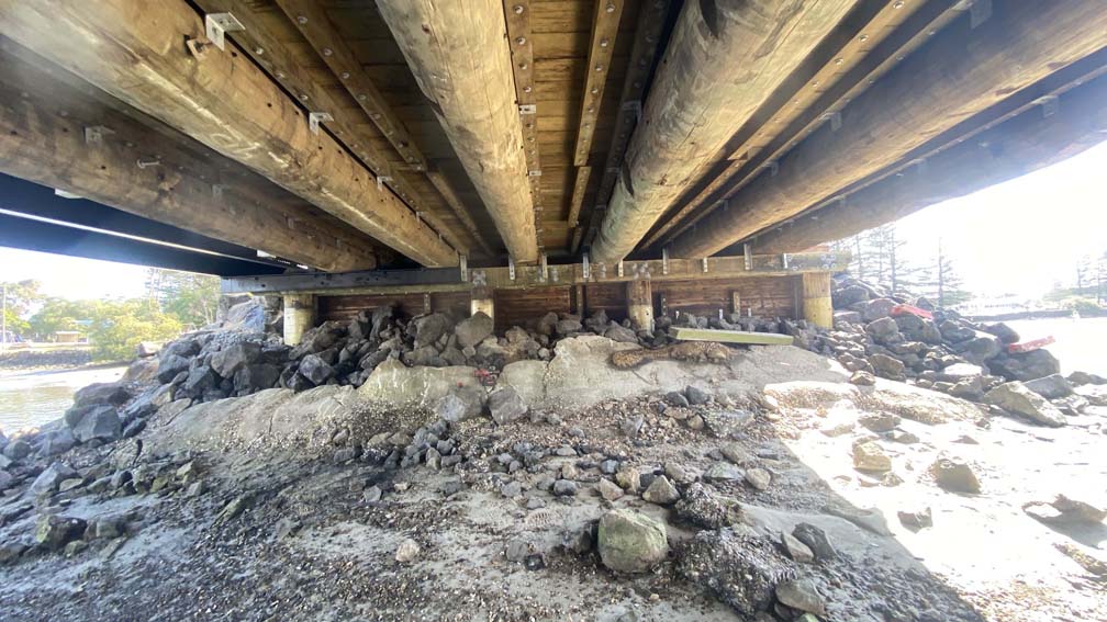
Final Project Photos
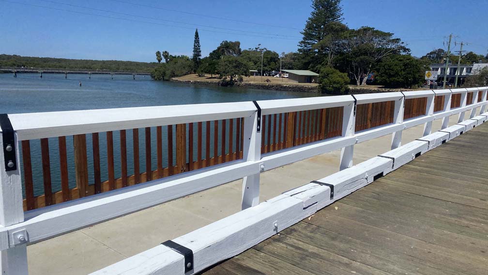
The South Arm Bridge was just completed, and the project was quite the feat. With countless hours, and a talented crew, this is a project to remember, and something we are very proud of! Take a look at more of the finished bridge below.
